Automatic control of AC bridge-based capacitive strain sensor interface for wireless structural health monitoring
This study addressed such limitations with critical updates in both hardware and software with fully automated features for high-sensitive capacitive strain sensing. Newly developed hardware and software are fully controlled with a low-cost microcontroller ATmega328p in an automated way
The authors previously developed a flexible strain sensor technology based on a soft elastomeric capacitor (SEC) for SHM and investigated an alternating current (AC) bridge-based method to transform the strain-induced dynamic capacitance changes in the SEC into analog voltage signals. Previous experiments have verified the capability of the SEC and the AC bridge-based signal converter for structural strain sensing applications. However, careful manipulation requirement for precise AC-bridge balancing, signal amplification control, and shunt calibration limits its practical use for full-scale SHM in field conditions. This study addressed such limitations with critical updates in both hardware and software with fully automated features for high-sensitive capacitive strain sensing. Newly developed hardware and software are fully controlled with a low-cost microcontroller ATmega328p in an automated way.
A recent research has developed an analog De Sauty bridge-based wireless capacitive strain sensor board (c-strain sensor board) that demonstrated extremely low-level capacitive strain sensing capability in a wireless manner [1]. It was successfully integrated with the high-fidelity smart sensing platform Xnode that provides various functionalities for high-sensitivity wireless SHM; Xnode functions include a solar-powered battery, low power consumption, 3.3V power supply, onboard signal processing, wireless communication, and 24-bit analog-to-digital conversion. The static and dynamic strain sensing sensitivity of the developed c-strain sensor board was validated via a series of lab tests. However, several practical limitations remain to be resolved for large-scale field implementations. The c-strain sensor board comprises full analog circuits; AC-bridge balancing, amplification, and a two-step shunt calibration process are required be done manually with an oscilloscope for high-frequency AC signal control prior to actual deployment for sensing to ensure high-quality measurement. However, such manual setup with the oscilloscope is cumbersome and is challenging in field conditions. Also, field engineers should have background knowledge of such sensor board pre-setup, such as precise AC bridge balancing and shunt calibration procedures, which is not desirable. Some studies has developed the automated AC bridge balancing techniques for easy capacitance sensing applications. However, none of these approaches deals with automated amplification and shunt calibration required for wireless SHM applications.

This study presents the development of a fully automated c-strain sensor board for wireless SHM applications, which can interface with the Xnode wireless sensor platform to be used under its 3.3V power for a measurement range of 0~2.4V. While keeping the basic capacitance measurement framework of the analog c-strain sensor board, we developed a low-cost microcontroller-based automated AC bridge balancing, amplification, and shunt calibration method. Peak-detection circuits and a 16 bit ADC were employed to read the peak voltages of the high-frequency AC signals. Digital potentiometers, digital bus switch, and an 8-bit microcontroller were employed to control the AC bridge balancing, signal amplification, and two-step shunt calibration. Embedded software was developed for automated control of the digital components. A prototype of the new sensor board was produced, and the performance was validated via lab tests and compared with a commercial wired capacitance measurement system.
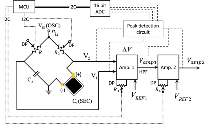
The bridge balancing should be designed precisely and proper amplification is required to ensure the maximum sensitivity without saturation. The high-frequency AC signal (\(V_{in}\),OSC) was excited using a 32.768 kHz square wave oscillator and converted to sine wave using a fourth-order Sallen-key filter. The AC bridge with two resistors and two capacitors known as the De sauty bridge was used. We employed a four-channel non-volatile digital potentiometer (AD5254 with 256-tabs 100 kΩ 4 CH, Analog devices) to directly control the bridge balancing and amplification via a microcontroller. Fig. 2 shows the detailed schematic diagram of the De sauty bridge, amplifiers, peak detection circuit, 16-bit ADC, and MCU. The digital potentiometer directly adjusts four resistances (\(R_{1~4}\)) for bridge balancing and amplifications.
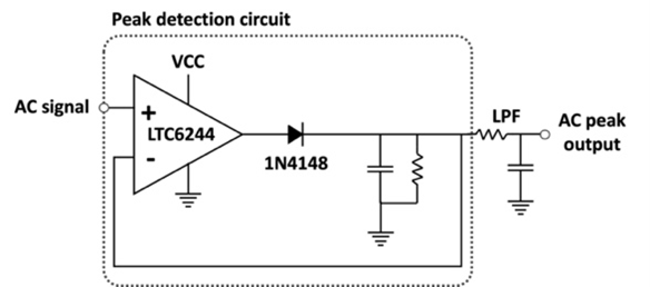
The balanced bridge configuration status is obtained when \(R_2/R_1=C_1/C_2\). \(C_1\) is the nominal capacitance of the SEC (DUT, device under test) and \(C_2\) is the reference capacitor. Two AC signals from the De sauty bridge and two AC signals from the two-step amplifiers (AD8226, Analog Devices), total of four AC signals are fed to the peak detection circuit shown in Fig. 3, which detects AC peak voltages. A total of four peak detection circuits were employed to detect AC peaks separately, targeting the 0–40 Hz frequency bandwidth. The four signals are fed into a 16-bit analog-to-digital converter (ADS1115, Texas Instruments) for precise peak voltage detection from the MCU with 0.1mV resolution (i.e., ADS1115 has 15-bit effective resolution). Fig. 6 shows an example of peak detection output that the peak of AC signal was precisely detected. The peak signals are feed to the ADC for precise voltage monitoring.
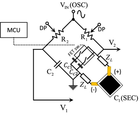
Shunt calibration is a key step to convert the voltage output to the desired unit for Wheatstone bridge-based sensing applications. Particularly in this application, the capacitance is affected by the parasitic capacitance (Z_L) in the lead wires that connect the SEC and AC De sauty bridge, as shown in Fig. 4, of which the parasitic capacitance effect needs to be effectively considered for accurate calibration. A recent study introduced the two-step shunt calibration strategy to avoid parasitic capacitance effect [1]. In this study, a field-effect transistor (FET) bus switch (SN74CBT, Texas Instruments), which can handle multiple switch channels, was employed for the automated two-step shunt calibration procedure.
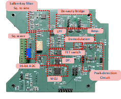
Fig. 5 shows the assembled prototype sensor board for performance validation. Each component has been described in Section 2 and consists of basic signal processing circuits, digital components, and peak-detection circuits.
Software development

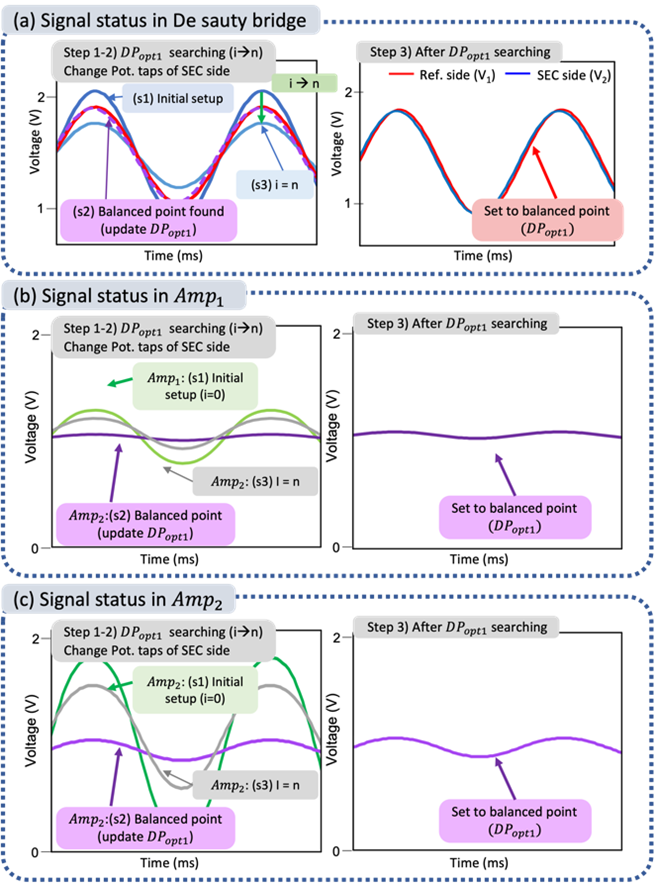
In addition to the hardware improvement, a new software framework was developed to implement the fully automated bridge balancing, signal amplification, and shunt calibration. The ATmega328P-AU (microchip) was used as a microprocessing unit (MCU). While the original clock speed is 16 MHz under a 5 V supply, the ATmega328P-AU was downclocked to 8 MHz to work under a 3.3 V supply with lower power consumption. Fig. 6 shows the flowchart of the fully automated De sauty bridge balancing, amplification, and shunt calibration procedures and Fig. 7. visualizes the automated bridge balancing procedure described above by showing the changes of the AC signals from the De sauty bridge.
Experimental validation
The performance of the developed sensor board was evaluated through lab-scale tests. A static noise test and a cantilever beam free-vibration test were conducted for performance validation. Two 3×3 in2 (7.6 × 7.6 cm2). SECs were used for a test having different nominal capacitance (SEC1: 326 pF, and SEC2: 335 pF) shown in Fig.6(a). Fig. 6(b,c) shows the detailed schematic of test setup.
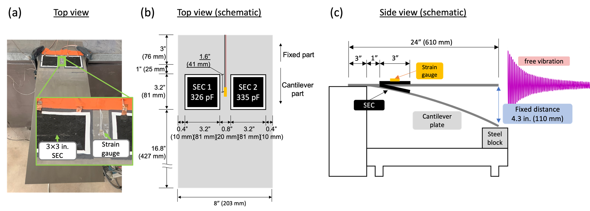
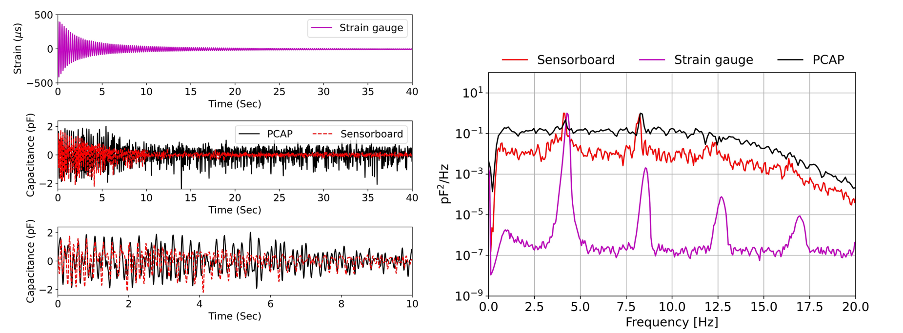
Fig. 7 shows a result of experiment from SEC2. the strain gauge measurements showed clear free-vibration responses and well caught the natural frequency peaks of the cantilever beam, of which expected first four frequencies are 4.15 Hz, 8.3 Hz, 12.45 Hz, and 16.6 Hz from the eigenvalue analysis, providing the reference information for the test. The test results from the PCAP and new sensor board connected to the SECs showed somewhat noisier measurements than strain gauge data, as expected, due to the SEC’s intrinsic characteristic prone to the electromagnetic field (EM) noise. But they showed a very similar trend at the initial stage when the vibration amplitude was large, i.e., around 0~5 seconds for both the SEC cases shown in Fig 7.
Also, Fig. 7. shows the cross power spectral density (CPSD) of each test case. The CPSDs of different metric measurements are compared based on the capacitance (power) unit (i.e. pF2/Hz) after converting all measurements in to pF unit.
While the strain gauge identified multiple clear peaks, including 4.3, 8.4, and 12.9 Hz, the new sensor board identified two~three peaks. Three peaks are clearly identified from the SEC1 case. However, the SEC2 case does not show clear peaks at 12.9 Hz. The PCAP was not able to identify clear peaks due to the high noise floor. The identified frequency peaks have minor differences with the strain gauge measurement caused by differences in the covered geometry area. Consequently, the new sensor board showed better performance compared to the PCAP over the whole frequency range.
Reference
[1] Jeong, J. H., Xu, J., Jo, H., Li, J., Kong, X., Collins, W., … & Laflamme, S. (2018). Development of wireless sensor node hardware for large-area capacitive strain monitoring. Smart Materials and Structures, 28(1), 015002.
More details can be found in the paper below:
Jeong, J. H., Jo, Hongki and Laflamme, Simon … & Jung, Hyung-Jo (2022). Automatic control of AC bridge-based capacitive strain sensor interface for wireless structural health monitoring, Measurement, elsevier (In press)